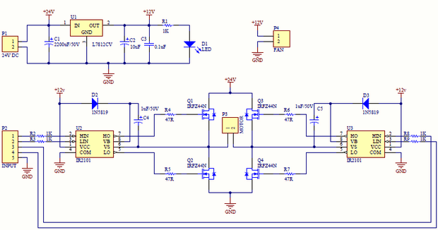
I will post a schematic that I use when I can. 9c7 Fet H Bridge Circuit Diagram Wiring Library. Solved 5 Explain The Principle Operation Of The H Bridge. Tutorial Experiment 7 Bi Directional Control Of Motors And The.
#H BRIDGE MOSFET DRIVER CIRCUIT DRIVER#
IE, turn on control A, and you will turn on the N-channel of the left side, and the P-channel of the right side (and vise versa). Simple H Bridge Motor Driver Circuit Using Mosfet. The DRV8706-Q1 is a highly integrated H-bridge gate driver, capable of driving high-side and low-side N-channel power MOSFETs. You can then tie in both inputs into a single control pin for 2 wire operation. Input A is Inverting, you should drive the P-channel fets with this, Input B is non-inverting to drive the N-channel fets. You should use 1 tc4428 to drive each side of the bridge. Circuit drive for level generation was created using optocoupler TLP250 and circuit driver for H-bridge was generated using IR2101. This will create a temporary shoot through state each time you switch that side on/off (as the voltage in the 4428 changes, there will be time when both the N-channel and P-channel will be at around 6-8 volts which will cause both fets on the same side of the h-bridge to be partially open at the same time). Your schematic shows that you are switching both the HIGH/LOW side fets with the same output. The TC4428 has 1 inverting output and 1 non-inverting output. I generally throw something like 220uF-330uF there. Some capacitance definitely helps, but I don't know of a definite sizing guide. A "big" capacitor for the motors.that is less well determined. There should be a capacitor close to the TC4428 (1uF ceramic or so). In case the Arduino outputs float, you don't want both TC4428 outputs turning on at the same time (that will destroy your MOSFET's very quickly). I would recommend pull-down resistors at the inputs of the TC4428.


4 shows an inverting driver (VIN 0 drives the MOSFET on and VIN 1 drives the MOSFET off). 3 shows a non-inverting driver (VIN 1 drives the MOSFET on and VIN 0 drives the MOSFET off) whereas Fig. 3, with the difference being that the circuit in Fig. VDD for the TC4428 should be 12V, not 5V. 4 is similar to the above circuit in Fig. I would keep the TC4428 (or similar) gate driver because FET's with high current handling and low on-resistance will generally have large gate capacitance, which is difficult to drive from a microcontroller and can even damage it over time due to high peak currents. You do not need logic-level FET's for the N-channel ones either if you are going to use a gate driver like the TC4428. You do not need a logic-level FET for the P-channel ones because their gate voltage will swing from 0V to 12V.


 0 kommentar(er)
